
Current Transformer Testing
Testing Procedures
|
Download: CT Test Format
|
Equipment Required
|
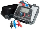
Insulation Tester
|
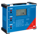
CT Analyzer
|
Multimeter
|
Insulation Resistance Test
- Use Megger mit1020 to measure insulation resistance.
- Insulation Resistance Tests to be done:
- Primary winding - Ground (Apply 5000V for 1 minute)
- Primary winding - Secondary winding (Apply 2500V for 1 minute)
- Secondary winding - Secondary winding (Apply 2500V for 1 minute)
- Secondary - Ground (Apply 1000V for 1 minute)
CT Characteristics Test
|
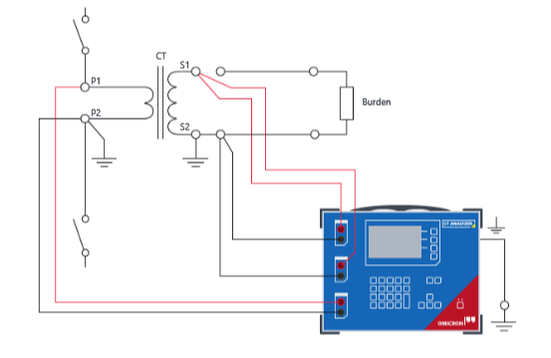
Connection Circuit
|
CT Loop Resistance Test
- Measure CT resistance from CT terminal blocks (CT Side).
- Measure Loop resistance from CT terminal blocks (Load Side).
- Measure the Total Loop resistance (CT resistance + Load resistance + wiring resistance).
CT Primary Injection Test
|
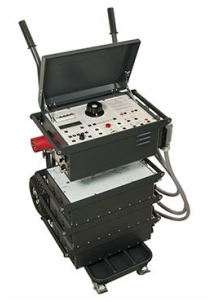
ODEN AT
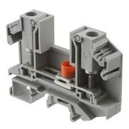
CT Terminal Block
|